Jual Dimmer pengatur kecerahan Lampu LED 12V 24V DC dimer Switch On Circuit Diagram In this LED Dimmer Circuit, 555 timer works as an astable multivibrator and generates PWM pulses. The circuit includes the timing components like Resistors, potentiometer, and capacitor Thus, the potentiometer is there to adjust the duty cycle of the PWM signal. The higher the duty cycle, the greater will be the light intensity, the light
Hii Friends, Today i am show you how to make a automatic light dimmer circuit at home. So let's start it. All Component details show in the video. So watch v

How to Make an Automatic Light Up LED Strip W/ Photocell Circuit Diagram
You'll make an automatic dimmer for an LED. Apart from sensors To create a closed circuit, the first leg of the LDR is connected to the 5 volt voltage and the last bit, the other leg of the resistor, is connected to the ground. Finally, you need one more wire to get some data from the sensor.
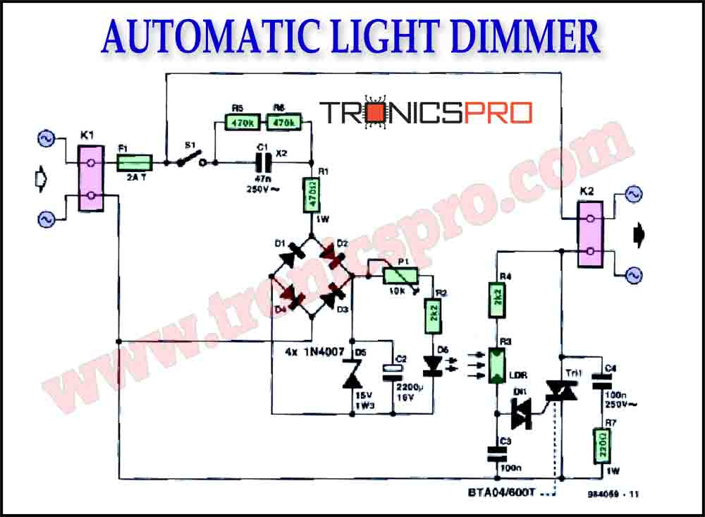
WORKING OF AUTOMATIC LAMP DIMMER CIRCUIT: Triac and LDR holds the significant place in the working of this lamp dimmer. Here LDR (Light Dependent resistor) was used as a light sensor which offers high resistance to the current flow in the absence of light and low resistance when light incident on it. PWM LED dimmer circuit using IC 555; USB However, the dimming effect can be perhaps implemented by connecting the series LED section of the LED bulb with the IC 555 circuit, as indicated in the following diagram: We know that an LED bulb circuit is nothing but a small AC to DC SMPS circuit, which employs a small ferrite transformer for stepping down the mains voltage to a lower LED DC
Automatic Light Dimmer Circuit Diagram
The automatic Daylight dimmer circuit. But in Figure 2 will work to reverse the first. Also, choose the switch-S2 to LDR1 way, then this circuit becomes the automatic daylight dimmer switch circuit. This can control lamps in the Warehouse, if open the door and have sunlight to LDR, it will cause the lamp to glow. LDR1 in Figure 2 is a PTC type.
