What Is Reflow Soldering Circuit Diagram Reflow soldering, on the other hand, is better suited for SMD-heavy assemblies, providing precise and consistent solder joints with minimal thermal stress on components. When choosing between wave soldering and reflow soldering, consider factors such as component types, production volume, PCB complexity, budget, equipment, and quality requirements.
Also, you can always manually solder or hand solder PCB components, but this will rarely be a good approach if you have access to one of the mechanical methods of soldering. Manual soldering would only be an alternative to reflow soldering, but reflow soldering is still far superior. More on Soldering and Printed Circuit Boards This video shows three different ways we solder electronic components to printed circuit boards: reflow, wave solder, and hand soldering. The Procedure of Reflow Soldering. Reflow soldering involves several critical preparation and assembly steps to ensure precise placement and bonding of components. Here is a detailed overview of the steps you need to follow in a reflow soldering station. 1. Preparation. The first stage is preparing the board and components for soldering.

Reflow Soldering Guide. Process, Oven and Advantages Circuit Diagram
And wave soldering equipment is more affordable than reflow ovens. Wave Soldering vs. Reflow Soldering: Applications. Wave soldering is ideal for welding through-hole components on circuit boards, while reflow works best for surface mount components. Wrap Up. As you can see, wave and reflow soldering differ immediately from the start.

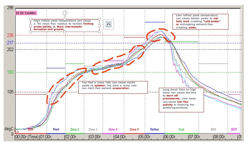
Unless you are soldering through-hole elements, reflow soldering is the most common method for many manufacturers (especially suitable for SMT assembly). Figure 1. The process of reflow soldering. The reflow solder process begins by applying flux and solder (also known as solder paste) to the pads.
Reflow Soldering vs Wave Soldering: What's the Difference? Circuit Diagram
On the other hand, industrial reflow machines are designed for mass production and can effectively solder a wider variety of components. Wave Soldering vs Reflow Soldering. Wave soldering and reflow soldering are complementary soldering techniques. In the chart below, you will find their main differences: